PicoScope 7 Software
Available on Windows, Mac and Linux
A to Z of PC oscilloscopes
Everything you need to know about PC oscilloscopes from Advanced Triggers to Zooming.

A to Z of Data Loggers
Everything you need to know about PC-based data loggers from Alarms to Zooming.
Application Notes
Details of some of the many applications for Pico data logger and oscilloscope products.

How do I measure...?
Find out how you can measure using Pico products

Videos
Showing you how to get the most out of PicoScope oscilloscope software.

Documentation
Up-to-date versions of the documentation supplied with your products in PDF format.

Educational Experiments
Our library of science experiments suitable for use with oscilloscope and data logging products.

PicoApps
Want to share hints, tips and code with other developers? Show your Pico-based products to the world.

Newsletter
Archive of our monthly Test and Measurement Newsletters.

An electrocardiogram or ECG (also known as EKG — abbreviated from the German word Elektro-Kardiographie), is an electrical recording of the heart and is used in the investigation of heart disease. This application note makes use of a DrDAQ Oscilloscope / Data Logger to read and store electrocardiograms but this can be subsituted by any of the PicoScope range of oscilloscopes.
British physiologist Augustus D. Waller was the pioneer of electrocardiography and in 1887 published the first human electrocardiogram. Yet in 1911 Waller said, "I do not imagine that electrocardiography is likely to find any very extensive use in the hospital. It can at most be of rare and occasional use to afford a record of some rare anomaly of cardiac action." However, just 13 years later, the Nobel Prize in Medicine was awarded to Dutch physiologist Willem Einthoven, who transformed this curious physiologic phenomenon into an indispensable clinical recording device that is still used today.
The electrocardiogram, or ECG / EKG is a surface measurement of the electrical potential generated by electrical activity in cardiac tissue. Current flow, in the form of ions, signals contraction of cardiac muscle fibres leading to the heart’s pumping action.
The ECG is a valuable, non–invasive diagnostic tool which was first put to clinical use in 1913 with Einthoven’s invention of the string galvanometer. The results below show a reproduction of one of Einthoven's original traces.
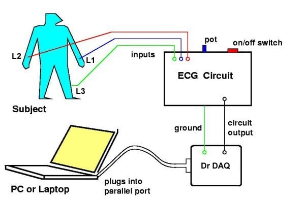
Einthoven’s recording is known as the "three lead" ECG, with measurements taken from three points on the body (defining the "Einthoven triangle" — an equilateral triangle with the heart at the centre.) The difference between potential readings from L1 and L2 is what is used to produce the output ECG trace. The L3 connection establishes a common ground for the body and the recording device (oscilloscope.)
Establishing the correspondence between the ECG trace and the electrical events in the heart is known as the inverse problem of electrocardiology: solving for the electric sources from the potential generated by those sources on the surface of the body.
The ECG device was constructed based on the "Amateur Scientist" article by Shawn Carlson that appeared in the June 2000 issue of Scientific American. That article describes the layout for a circuit based on an instrumental amplifier that can be used to measure the ECG.
The circuit was built with some modifications as described below, and a DrDAQ data acquisition card was used to read out the output signal into a laptop, which effectively functions as a storage scope. The basic setup is illustrated below.
The graphs below show sample traces that were captured using Einthoven’s three&ndsah;lead ECG method


Electricity can kill – if you wish to try this project yourself then please read the safety issues first.
As previously mentioned, the electronic circuit for the ECG application is similar to the one described in Shawn Carlson’s Scientific American article. The circuit diagram is shown below. At the heart of it is an AD624AD Instrumentation Amplifier from Analog Devices.
The amplifier takes inputs from self-sticking electrodes that are attached to the body of the subject whose ECG is being taken. Because the signals are small, and the amplifier can be susceptible to various noise sources, it is important for the cables connecting the electrodes to the inputs of the circuit (shown as the blue, red and green circles in the diagram) to be (1) as short as possible and (2) well shielded. RG-174 50 Ohm coaxial cables with lemo connectors were chosen as these cables are good to use for this project because they are sturdy, yet thin and light, and the lemo connectors are easy to plug and unplug into the aluminum sheet metal box that was used to house the circuit.
Because of the safety issues associated with electrically connecting a person to an electronics device that runs off a significant power source, diode protection was added to the inputs to the amplifier. The circuit shown above only runs off of two 9 volt batteries, which themselves don’t constitute a "significant power source", however an oscilloscope or computer to which the output of the amplifier is connected will in general be powered by the line voltage from a wall socket. If for some reason there is a power surge that causes something catastrophic to happen in the oscilloscope or computer, it is imaginable that the line voltage could be transmitted through the amplifier to its inputs. Although this scenario is unlikely, the diode connections to ground should in principle route the current to ground since it takes only 0.6 volts across the diode before it acts as a short circuit. The 0.6 volts is much larger than the electrical signals coming from the heart, so this shouldn’t affect the performance of the circuit. Also, you need two oppositely oriented diodes for each input – one to carry current during positive voltage swings, and one for negative voltage swings. Alternatively, to improve safety the circuit could be redesigned and the protection diodes replaced with an optoisolator circuit —this would provide complete galvanic isolation (up to several thousand volts) between the electrodes and the power supply.
For the output signal, a bulkhead BNC connector was mounted on the box containing the circuit so that the output could be connected directly to an oscilloscope via correctly terminated 50 Ohm coax cable.
The output part of the circuit is modified relative to the Scientific American article so that the output could be connected to the DrDAQ ADC which has a dynamic range for voltages between 0 and 5 volts. This is not well matched to the ECG signal which has both positive and negative–going pulses. Consequently it was necessary to AC–couple the output of the amplifier with the 1µF capacitor shown, and add a pull–up resistor connected to the +9 volt supply to bring the DC level to a positive value of about 2 volts (see sample traces above). A 680 k ohm resistor was used since the resistance across the ADC (forming the other leg of the voltage divider) measured to be about 180 k ohms.
Two 9 volt batteries were used for the power supply for the amplifier (as well as for the pull–up of the output signal). The relevant terminals of the batteries were connected to a switch mounted on the chassis for ease of powering up and down. Decoupling capacitors were also used.
The grounds of the circuit and the input and output cables were connected to the metal box housing the circuit and insulating feet were fitted to the box. The idea in this is that the ground for the circuit will then come from whatever device is looking at the output — either the oscilloscope or computer. Since these devices are usually powered from the line voltage, the ground from the wall socket often provides a very good ground connection.
However, as noted in the safety issues section, one should be very wary about connecting a home-built circuit to something that is running off a significant power source. In principle, one can more safely read out the circuit using a laptop computer that is running off its battery. However, this leaves the laptop’s ground floating, and without a good ground connection it was found that there was a tremendous amount of noise, and the ECG signal became completely obscured. If the circuit can be connected to a good ground connection then using a battery–powered laptop should work well.
Even with the laptop plugged into the mains socket, a significant amount of noise was still found. It was found that the best results were obtained by keeping the cables connecting the subject to the circuit close together, thereby reducing inductive pickup.
As an enhancement to this project additional noise reduction measures could be investigated.
It is imperative that anyone who wishes to try this application have a good understanding of safety protocols.
As mentioned in the section on the electronic circuit, when you connect your body to any electronic device, you must be much more careful than you usually are with your standard home electronics, because it can be extremely easy to cause a serious and even fatal electric shock.
Placement of the electrodes on the body, provides an excellent path for current flow — the measured impedance between leads L1 and L2 is approximately 50 k ohms.
Professionally built medical devices are built with significant overvoltage protection so that line power glitches do not represent a hazard to patients — for this application diodes are used to provide limited over–voltage protection. To further increase safety an optoisolator intergrated circuit could be added to the existing circuit so that the subject is completely isolated from the power supply.
It is not recommended that you use this ECG device during an electric storm.
You should not attempt to use such a setup as that described here unless you are knowledgeable about and comfortable with using electricity in a safe and controlled manner.
The information for this application was kindly provided by Sima Setayeshgar — Science and Technology Council Postdoctoral Fellow of Princeton University