PicoScope 7 Software
Available on Windows, Mac and Linux
A to Z of PC oscilloscopes
Everything you need to know about PC oscilloscopes from Advanced Triggers to Zooming.

A to Z of Data Loggers
Everything you need to know about PC-based data loggers from Alarms to Zooming.
Application Notes
Details of some of the many applications for Pico data logger and oscilloscope products.

How do I measure...?
Find out how you can measure using Pico products

Videos
Showing you how to get the most out of PicoScope oscilloscope software.

Documentation
Up-to-date versions of the documentation supplied with your products in PDF format.

Educational Experiments
Our library of science experiments suitable for use with oscilloscope and data logging products.

PicoApps
Want to share hints, tips and code with other developers? Show your Pico-based products to the world.

Newsletter
Archive of our monthly Test and Measurement Newsletters.

PicoScope® 3000 Series
Power, portability and performance


PicoScope 3000 Series USB-powered PC oscilloscopes are small, light, and portable and can easily slip into a laptop bag while offering a range of high-performance specifications.
These oscilloscopes offer 2 or 4 analog channels and a built-in function / arbitrary waveform generator. MSO models add 16 digital channels. Key performance specifications:
Supported by the advanced PicoScope software, these devices offer an ideal, cost-effective package for many applications, including embedded systems design, research, test, education, service, and repair.

Despite a compact size and low cost, there is no compromise on performance with bandwidths up to 200 MHz. This bandwidth is matched by a real-time sampling rate of up to 1 GS/s, allowing detailed display of high frequencies. For repetitive signals, the maximum effective sampling rate can be boosted to 10 GS/s by using Equivalent Time Sampling (ETS) mode.
Other oscilloscopes have high maximum sampling rates, but without deep memory they cannot sustain these rates on long timebases. The PicoScope 3000 Series offers memory depths up to 512 million samples, more than any other oscilloscope in this price range, which enables the PicoScope 3406D MSO to sample at 1 GS/s all the way down to 50 ms/ div (500 ms total capture time).
Managing all this data calls for some powerful tools. There’s a set of zoom buttons, plus an overview window that lets you zoom and reposition the display by simply dragging with the mouse or touchscreen. Zoom factors of several million are possible. Other tools such as the waveform buffer, mask limit test, serial decode and hardware acceleration work with the deep memory making the PicoScope 3000 series some of the most powerful oscilloscopes on the market.
The PicoScope 3000D Series Mixed-Signal Oscilloscopes include 16 digital inputs so that you can view digital and analog signals simultaneously.
The digital inputs can be displayed individually or in named groups with binary, decimal or hexadecimal values shown in a bus-style display. A separate logic threshold from –5 V to +5 V can be defined for each 8-bit input port. The digital trigger can be activated by any bit pattern combined with an optional transition on any input. Advanced logic triggers can be set on either the analog or digital input channels, or both to enable complex mixed-signal triggering.
The digital inputs bring extra power to the serial decoding options. You can decode serial data on all analog and digital channels simultaneously, giving you up to 20 channels of data. You can for example decode multiple SPI, I²C, CAN bus, LIN bus and FlexRay signals all at the same time!
Application note: Debugging an I²C Bus with a PicoScope Mixed–Signal Oscilloscope
Mixed Signal Oscilloscope / Logic Analyzer (roll over red circles for description)
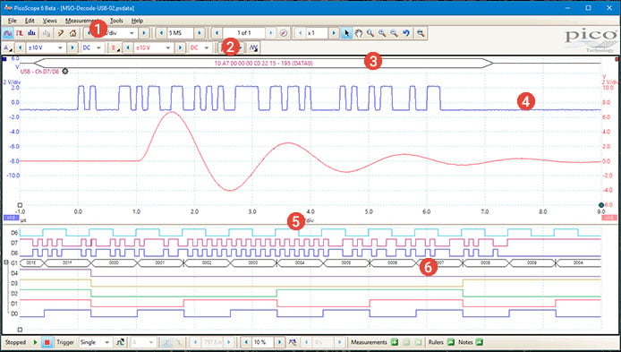

PicoScope can decode 1-Wire, ARINC 429, CAN & CAN FD, CAN XL, DALI, DCC, DMX512, Ethernet 10Base-T and 100Base-TX, FlexRay, I²C, I²S, I3C, LIN, PS/2, Manchester, MIL-STD-1553, MODBUS, SENT, SPI, Parallel Bus, PMBus, Quadrature, SBS Data, SENT Fast/Slow, SMBus, SPI MISO/MOSI, SPI SDIO, UART (RS-232 / RS-422 / RS-485), and USB 1.1 protocol data as standard, with more protocols in development and available in the future with free-of-charge software upgrades.
Graph format shows the decoded data (in hex, binary, decimal, or ASCII) in a data bus timing format, beneath the waveform on a common time axis, with error frames marked in red. These frames can be zoomed in to investigate noise or signal integrity issues.
Table format shows a list of the decoded frames, including the data and all flags and identifiers. You can set up filtering conditions to display only the frames you are interested in or search for frames with specified properties. The statistics option reveals more detail about the physical layer such as frame times and voltage levels. PicoScope can also import a spreadsheet to decode the data into user-defined text strings.
More information on Serial bus decoding and protocol analysis - overview >>

All PicoScope 3000D units have a built-in function generator (sine, square, triangle, DC level, white noise, PRBS etc.) on the front panel. PicoScope 3000D MSO models have the connector on the rear panel.
As well as basic controls to set level, offset and frequency, more advanced controls allow you to sweep over a range of frequencies. Combined with the spectrum peak hold option this makes a powerful tool for testing amplifier and filter responses.
Trigger tools allow one or more cycles of a waveform to be output when various conditions are met such as the scope triggering or a mask limit test failing.
A 14 bit 80 MS/s arbitrary waveform generator (AWG) is also included. AWG waveforms can be created or edited using the built-in AWG editor, imported from oscilloscope traces, or loaded from a spreadsheet.

Increasing the number of points in a FFT to 1 million increases frequency resolution and reduces the noise floor.
The spectrum view plots amplitude against frequency and is ideal for finding noise, crosstalk or distortion in signals. The spectrum analyzer in PicoScope is of the Fast Fourier Transform (FFT) type which, unlike a traditional swept spectrum analyzer, can display the spectrum of a single, non-repeating waveform.
A full range of settings gives you control over the number of spectrum bands (FFT bins), window types, scaling (including log/log) and display modes (instantaneous, average, or peak-hold).
You can display multiple spectrum views alongside oscilloscope views of the same data. A comprehensive set of automatic frequency-domain measurements can be added to the display, including THD, THD+N, SNR, SINAD and IMD. A mask limit test can be applied to a spectrum and you can even use the AWG and spectrum mode together to perform swept scalar network analysis.

Most oscilloscopes are built down to a price. PicoScopes are built up to a specification.
Careful front-end design and shielding reduces noise, crosstalk and harmonic distortion. Years of oscilloscope design experience can be seen in improved bandwidth flatness and low distortion.
We are proud of the dynamic performance of our products, and unlike most oscilloscope manufacturers publish our specifications in detail. The result is simple: when you probe a circuit, you can trust in the waveform you see on the screen.

The USB connection not only allows high-speed data acquisition and transfer, but also makes printing, copying, saving, and emailing your data from the field quick and easy. USB powering removes the need to carry around a bulky external power supply, making the kit even more portable for the engineer on the move.
PicoScope 3000 Series oscilloscopes feature a SuperSpeed USB 3.0 connection, making the already-optimized process of data transfer and waveform update rates even faster. Further benefits of a USB 3.0 connection include faster saving of waveforms and faster gap-free continuous streaming of up to 125 MS/s when using the SDK, while the scope is still backward-compatible with older USB systems.


